The Superior Works: Patrick's Blood and Gore Planes #46 - #54
Quick Find: #46, #47, #48, #49, #50, #51, #52, #53, #54
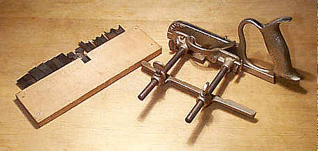
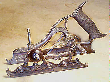
#46 Adjustable Dado and Plow Plane, 10 1/2"L, various widths, 5 3/4lbs, 1874-1942.
 This plane was designed by Justus
A. Traut, a German immigrant, who was generally known as "The Patent King
of the United States." He held at least 145 patents, ranging from
woodworking tools to bottle openers. He held the basic patent for the #45, but this, and the following plane, the #47, are commonly known as "Traut's Patent
Combination Plane".
This plane was designed by Justus
A. Traut, a German immigrant, who was generally known as "The Patent King
of the United States." He held at least 145 patents, ranging from
woodworking tools to bottle openers. He held the basic patent for the #45, but this, and the following plane, the #47, are commonly known as "Traut's Patent
Combination Plane".
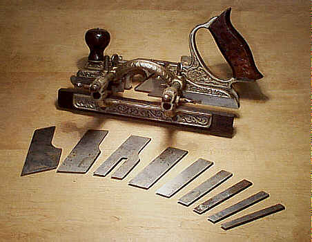
This is yet another in a series of combination planes offered by Stanley. The distinguishing characteristics of this plane is that it has fewer cutters, all of which are ground straight across, and that they are skewed, which makes the plane more versatile when used across or against the grain. Most of the planes are found missing all but one of their cutters, with the only one present being the one left in the plane from the last time it was used. Cutters from the other combination planes will not work in this one as the edges of the #46's cutters are beveled (relative to the cutter face). If you need cutters, you often will pay more for a complete set than you did for the plane itself.
Like the #45, this plane originally was cast with floral motifs on its main stock, sliding section, and fence. Prior to the addition of its #45-like fence, which was introduced ca. 1900, the sliding section doubled as the fence when the plane was used for ploughing and rabbeting. A detachable guard plate, which is often missing from the plane, was screwed to the sliding section's skate for this function. The guard plate extends the depth of the sliding section so that it can reference the edge of the stock and position the cutter at a constant distance from the edge. If you note two holes in the sliding section, and there's nothing filling them, your plane had a detachable guard plate, which long ago became detached from your plane. A lot of guys are looking for guard plates, and the screws that hold them to the plane (they are rather fragile), so you'll have plenty of shoulders to cry on while hunting for yours. Do be sure that you're after the proper guard plate as there is a very subtle difference between them where the earlier ones have small thumb screws to fasten the guard plate to the sliding section and the later ones have slotted screws to accomplish the same. Test that your guard plate's inner face is flush with the inner face of the sliding section, when the guard plate is attached.
 Another commonly missing
part is the wrap around depth stop, which came with the earlier models of the
plane. This fence, made of cast iron, straddles the main stock and fits over
the top of the regular depth stop. This stop is superflous, and many guys just
tossed them, using just the regular depth stop instead. This wrap around depth
stop is probably the hardest part to find for this tool. And while on missing
parts, it should be noted that this plane only came with a single depth stop
(unlike the #45) and that only one thumb
screw was supplied to secure the depth stop; there are two positions for the
depth stop and it and its screw are swapped to the desired location.
Another commonly missing
part is the wrap around depth stop, which came with the earlier models of the
plane. This fence, made of cast iron, straddles the main stock and fits over
the top of the regular depth stop. This stop is superflous, and many guys just
tossed them, using just the regular depth stop instead. This wrap around depth
stop is probably the hardest part to find for this tool. And while on missing
parts, it should be noted that this plane only came with a single depth stop
(unlike the #45) and that only one thumb
screw was supplied to secure the depth stop; there are two positions for the
depth stop and it and its screw are swapped to the desired location.
After the guard plate was dropped for the fence proper, the plane pretty much followed the #45 in its evolution - the plane dropped the japanning in favor of the flashy nickel plating ca. mid 1890's, a rosewood strip was added to the fence ca. 1905, the rosewood handle style changed over time, etc... One notable difference is that the rosewood front knob always remained on the main stock, and was not repositioned onto the fence as in the case of the #45. Also, the floral casting was continued on the #46 until its production was KO'ed permanently during the big war.
When the guard plate is removed from the plane, which is what's done when cutting dados, a batten must be used to track the plane. The batten is tacked along the right side of the dado's position on the wood so that the right side of the plane has a consistant reference to cut the dado. The depth stop is positioned on the sliding section, which is opposite when grooving or rabbeting where the depth stop is positioned on the main stock. The spurs - one on the sliding section and one on the main stock - are lowered so that they can score the wood prior to the cutter doing its cutter thing. The spurs are arranged so that their bevels face each each other. It's surprising how many planes can be found with the spurs turned around with the bevels facing outward from the cutter. Speaking of spurs, many of the planes are missing theirs. Like the guard plate, there are two basic kinds of spurs: those that are wedged into milled slots and those that are secured with a small screw. The latter spurs are the easiest to use, and they can be flipped end for end when one end of the spur no longer has any more life left to it.
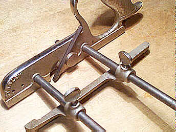
The plane should be inspected for cracks or repairs to the castings. The plane is a rugged one, but like any other piece of cast iron, it cannot withstand body slams to concrete or the like. Check the looping portion of the casting about the handle, the casting on the fence where the arms arch upward, and the skates of the main stock and sliding section. On this plane, and the #47, the skates are cast integral to the plane and are not made of steel pieces pinned the castings like they are on the #45 and #55. You should also unscrew the arms to make sure that they aren't bent
This plane is a fabulous worker, much better than the #45. The simple act of skewing the iron makes this plane plane dados around the #45. It also does a fine job of cutting cross grain rabbets, a common function when making lipped drawer fronts. If you have money burning a hole in your pocket, and are given the chance to buy one, and you dig working wood with handtools, buy this tool! A good working example of this plane will cost less than the number of wooden dado planes alone that it replaces. And, unlike the wooden dado planes, this one won't warp on ya, which is the kiss of death for wooden dados (warped wooden dados will have your dados in a bind).
There is one minor nuisance that bugs me about the plane - I find that its arms are too long for cutting dados. The arms need to be as long as they are so that the tool can cut grooves over the same range that common ploughs do. Stanley must have recognized that the long arms bugged other guys since they quickly added the #47, with its shorter arms, to their arsenal of planes. And while on the topic of arms, make sure that the arms are proper and not replacements off a #45. The #46 arms measure 5" long (not counting the threaded length) on the earlier models, while the later models (the later production of the nickel plated examples) have arms of 6 1/2" long.
The following cutters come with the plane:
Cutters First Offered in 1874
|
ploughing and dadoing |
3/16", 1/4", 5/16", 3/8", 1/2", 5/8", 7/8", 1 1/4" |
|
fillister |
1 1/2" |
|
tonguing |
1/4" |
Cutter First Offered in 1884
|
slitting cutter |
V-shaped (same as that of the #45) |
Cutter First Offered in 1919
|
ploughing and dadoing |
13/16" |
Again, you'll note the presence of the mysterious 13/16" width, which appeared simultaneously with the cutter provided for the #45 and the introduction of the #39 13/16. The astute observer will also note that Stanley never offered a 3/4" cutter with the plane. Kinda makes it tough on us modern woodworkers, no?
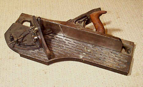
#47 Adjustable Dado Plane, 10 1/2"L, various widths, 3 3/4lbs, 1876-1923. *
 This plane is a funky
hybrid of the #46, and was designed to function
only as a dado plane as evidenced by the short 4" arms that are provided
with the plane. The arms are only long enough to accomodate the widest cutter
and the sliding section. The plane is never marked #47, since the #46 casting was always supplied as the plane. In fact,
the plane is embossed "No. 46".
This plane is a funky
hybrid of the #46, and was designed to function
only as a dado plane as evidenced by the short 4" arms that are provided
with the plane. The arms are only long enough to accomodate the widest cutter
and the sliding section. The plane is never marked #47, since the #46 casting was always supplied as the plane. In fact,
the plane is embossed "No. 46".
Other than the conspicuous short arms - they measure 2 1/2" long over the unthreaded portion - there are two other distinguishing ways to identify the plane: 1) the front right housing for the depth stop is ground off; 2) and the sliding section never has holes to receive the guard plate (remember, the guard plate is used only for ploughing and rabbeting on the #46). The depth stop is always positioned in the sliding section, to the left of the cutter, just like it is on a wooden dado.
A fence was never supplied with the plane, nor were there as many cutters supplied, but both these facts are no guarantee that you have a true #47. It gets very confusing on the last models of this plane, since they are identical in every way to the #46, except that they were shipped without the fence, have fewer cutters, and the rightmost depth stop housing is not ground off. These planes are always nickel plated. I'd be wary of these later models, if you're collecting, unless they come along with their original box marked with a #47 label.
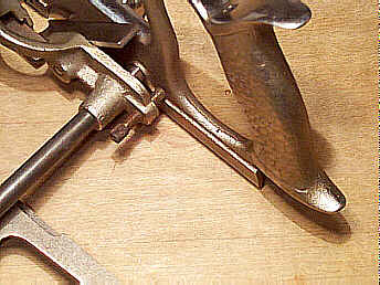
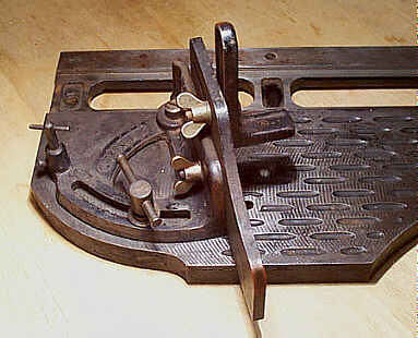
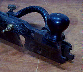 I discovered a very rare
variant of the #47, and it's surprising the thing was never offered this
way (and on the #46, too). There is a problem with
both the planes when using the narrowest cutter - only one spur, the rightmost
(carried on the main casting), can be used as it's impossible to move the
sliding section close enough to align with the cutter's leftmost edge. This is
obviously suboptimal. On the one example I unearthed, Stanley milled an extra
recess on the left side of the main casting for an auxilary spur thus making it
possible to remove the spur from the sliding section and placing it in the main
casting (you can see the extra recess in the image to the right - the recess is
directly below the flat milled area). The narrowest cutter now has a spur
aligned with either side of the cutter, making the plane function as it should.
Perhaps Stanley found this milling too costly, and it seems odd that only one
example has turned up, which suggests that maybe it was a custom order by a
smart-thinking tradesman.
I discovered a very rare
variant of the #47, and it's surprising the thing was never offered this
way (and on the #46, too). There is a problem with
both the planes when using the narrowest cutter - only one spur, the rightmost
(carried on the main casting), can be used as it's impossible to move the
sliding section close enough to align with the cutter's leftmost edge. This is
obviously suboptimal. On the one example I unearthed, Stanley milled an extra
recess on the left side of the main casting for an auxilary spur thus making it
possible to remove the spur from the sliding section and placing it in the main
casting (you can see the extra recess in the image to the right - the recess is
directly below the flat milled area). The narrowest cutter now has a spur
aligned with either side of the cutter, making the plane function as it should.
Perhaps Stanley found this milling too costly, and it seems odd that only one
example has turned up, which suggests that maybe it was a custom order by a
smart-thinking tradesman.
Like the #46, these planes work marvelously for dadoing and do so without the risk of ripping your fingers to shreads like those 'lectrical ones can. The #47 isn't encountered nearly as often as the #46 is, and it's a plane that gets little respect by collectors and users. Do your part to change this by adopting one that happens along your way.
The following cutters come with the plane:
Cutters First Offered in 1876
|
dado |
3/8", 1/2", 5/8", 7/8", 1 1/4" |
Cutter First Offered in 1884
|
slitting cutter |
V-shaped (same as that of the #45) |
Cutter First Offered in 1919
|
dado |
13/16" |
Hey, there's that funky and whacky 13/16" cutter again! JANE, STOP THIS CRAZY THING!
#48 Tonguing and Grooving Plane, 10 1/2"L (8 3/4"L 1939 0n), 5/16"W, 2 3/4lbs, 1875-1944.
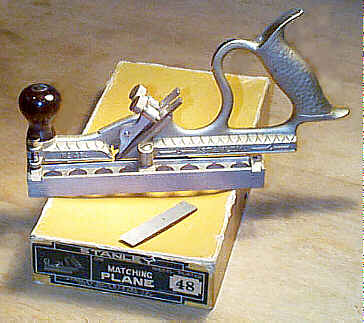 This is one of Stanley's better
planes to use, and even the most ham-fisted power tool junkie can handle this
plane and be amazed by its results. It works well, is practically
indestructable, and is very versatile - it is designed to work stock from 3/4"
to 1 1/4" in thickness (the groove centers on stock 7/8"). The only
general negative about the plane is that its tote is all metal, which makes for
some discomfort when using the plane in colder weather - metal sucks the heat
right out of your hands.
This is one of Stanley's better
planes to use, and even the most ham-fisted power tool junkie can handle this
plane and be amazed by its results. It works well, is practically
indestructable, and is very versatile - it is designed to work stock from 3/4"
to 1 1/4" in thickness (the groove centers on stock 7/8"). The only
general negative about the plane is that its tote is all metal, which makes for
some discomfort when using the plane in colder weather - metal sucks the heat
right out of your hands.
There are two separate lever caps, one on each side of the main casting, to hold the cutters in place. They are both activated by dedicated knurled screws. Examine these lever caps for any damage since they are somewhat fragile. The most common damage to them is breakage down where the cap places pressure on the cutter. Make sure that ends of the lever caps are not flared away from the main casting too much. If they are, the plane is apt to choke since the shaving can become lodged between the lever caps and the main casting. I can't recall seeing a plane with the lever caps butted perfectly against the main casting - they all have some degree of flaring to their lever caps - but some flare more than others. The nickel plated models seem to have lever caps that flare outward more than the earlier japanned models do.
This plane normally is found with just two cutters, each 5/16" wide. The original cutters of these planes do not have a circular notch cut on their right side up toward the top. If you see one that does, it's a cutter from a later #45; the notched cutters fit the plane perfectly and work as well as non-notched ones, but if you're into originality you'll need to find a cutter without the notches.The early #45's cutters don't have the cutout, and if one of these are used as a replacement cutter, it's impossible to tell whether the cutter is original to the plane.
An extra wide cutter (5/8") was also shipped with this plane, making for a total of three cutters on complete examples. The wide cutter is positioned into the right side of the plane so that it can cut tongues on thicker stock. If this cutters isn't with the plane anymore, you can still cut tongues on wide stock, but you'll need to remove the narrow strip of remaining wood on the rightmost side of the wood with a small bench plane or whatever else you use for lightweight trimming.
To the left of the cutters is a fence, which can be rotated end for end about its midpoint. There is a little locking pin on the forward portion of the main casting, just below the knob, which engages the fence to lock it in position. Check that this pin is there and that it works properly (there is a coil spring on the pin to keep it in place). When the fence is locked in one position, both cutters are exposed, and, thus, cut the tongue. When the fence is swung end for end, and locked into its other position, only one cutter is exposed, which then cuts the groove.
The fence can sometimes become wobbly from years of use. On these planes there is generally evidence of a quick fix, where the screw that holds the fence to the main casting is munged from over-tightening. You can also find washers jammed between the fence and main casting to make the fence steady.
There is a turned rosewood knob on the front of the plane, and a cast closed tote, both of which allow the plane to be worked easily. The knob is prone to chipping about its base, and you'll sometimes find some hack repair jobs to the nut and rod that fastens the knob to the main casting. The early models of the plane, those that are japanned, have the characteristic bead turned at the base of the knob.
 The plane, when put in
full production, was japanned, with brass lever cap screws (for the cutters).
Most of these earlier japanned models have the patent date, "PAT JULY 6,
1875", depressed below the handle. A few of the earliest japanned models
do not have the depressed date, but, instead, have "PATENTED / JULY 6.
1875 stamped into the sole on two lines. The date on these earliest planes is
very tiny and is not noticeable with a casual glance. However, the fence on the
earliest model is about 2/3rd's the thickness as that of the more common
japanned models; the earliest being 7/16" and the later being 3/4".
The thinner fence probably didn't offer enough lateral stability to the plane
during use, and thus was increased to the thicker 3/4". The earliest
planes have a pronounced bead turned at the bottom of the rosewood knob.
The plane, when put in
full production, was japanned, with brass lever cap screws (for the cutters).
Most of these earlier japanned models have the patent date, "PAT JULY 6,
1875", depressed below the handle. A few of the earliest japanned models
do not have the depressed date, but, instead, have "PATENTED / JULY 6.
1875 stamped into the sole on two lines. The date on these earliest planes is
very tiny and is not noticeable with a casual glance. However, the fence on the
earliest model is about 2/3rd's the thickness as that of the more common
japanned models; the earliest being 7/16" and the later being 3/4".
The thinner fence probably didn't offer enough lateral stability to the plane
during use, and thus was increased to the thicker 3/4". The earliest
planes have a pronounced bead turned at the bottom of the rosewood knob.
Ca. 1900, the plane was nickel-plated, and is the most commonly encountered version of it. These nickel plated planes can be found with and without the floral motif cast into the tote; the earlier nickel plated models have the vines, while the later nickeled models have the fish scale pattern cast into the tote. World War II era planes are japanned due to the shortage of nickel, and are fairly scarce. It's very easy to distinguish the earlier japanned models from the later World War II japanned models - the earlier models have a vine decoration cast into their totes whereas the World War II models have the fish scale-like casting to them. Further, the World War II models don't have any patent date information on them.
During this plane's production, and the #49's as well, it was equipped with more variations of lever cap screws than perhaps any other plane made by Stanley. Nicely knurled brass screws, slotted brass screws, nickeled screws cast with coarse knurling, nickeled screws with fine knurling, and slotted trumpet horn-shaped nickeled screws can all be found on these planes. The order in which they are listed appears to be the chronology in which Stanley used them. Only the japanned models used the brass screws.
There are some very scarce models of this plane, made by Union Manufacturing Company of New Britain, Connecticut, which Stanley modified and then sold under their name (Stanley had a 'incestuous' relationship with Union and finally bought out their entire plane line ca. 1920). These planes resemble the later nickel plated Stanley-manufactured #48's, but have black japanning in the depressions of the tote and the fence. Stanley ground off the UNION name (cast in the handle) and their model numbers (cast in the fence) from the plane, and then filled the areas with the japanning. Remnants of the Stanley decal can sometimes be found applied to the japanned area of the handle. They also did the same treatment on the narrower #49's made by Union.
An early 'prototype', which may have served as the inspiration for this plane, is cast with an integral fence; i.e., it doesn't flip end for end. It has much more detailed floral motifs cast into it than the conventional models of this plane. This plane was patented by Charles Miller, the same guy who designed the famous #41 through #44, and the first model #50. Miller, undoubtably, had to be familiar with the wooden match planes that have both the tongue and groove functions built into them, and from these he likely modeled this metallic prototype.
#49 Tonguing and Grooving Plane, 10"L (9"L 1937 on), 3/16"W, 2 3/4lbs, 1877-1944.
This plane is identical to the #48, except for the width of its cutters, each of which measures 3/16" wide (it, too has an extra and wider cutter so that it can work thicker stock). It is designed to work stock 3/8" to 3/4" thick, and centers its groove on stock 1/2" thick. It's less common than the #48. Like the #48, the early models are japanned, with the later ones nickel plated. The true type 1 has the patent date stamped into the sole of the plane, not depressed in the casting directly below the tote. I can't recall seeing a japanned World War II model of this plane, but I'm sure they must exist.
The plane was shortened by about an inch during the late 1930's. These shorter examples are not found nearly as often as the earlier and longer examples. Furthermore, the planes really aren't as long as the propaganda claim (which I use as a reference above). They are really closer to 8" long. These short planes have the smaller, slotted, trumpet horn-shaped, and nickel plated screws.
#50 Adjustable Beading Plane, 9 1/4"L, various widths, 3 1/2lbs, 1884-1962.
 This is another combination
plane, though not nearly as complex, nor heavy, as the #45. When it was offered in its first full
production, it was done so only as a beading plane, but someone got clever and
decided it could also function as a ploughing plane with little modification.
The plane seemed always to be in a state of change, as Stanley was adding this
or changing that on the tool over its lifetime of production. Since there are
numerous parts to this plane, and because it didn't come packed in a rugged box
- cardboard was the common material, but there was a short time when it was
offered in a metallic box - the plane is often found missing parts.
This is another combination
plane, though not nearly as complex, nor heavy, as the #45. When it was offered in its first full
production, it was done so only as a beading plane, but someone got clever and
decided it could also function as a ploughing plane with little modification.
The plane seemed always to be in a state of change, as Stanley was adding this
or changing that on the tool over its lifetime of production. Since there are
numerous parts to this plane, and because it didn't come packed in a rugged box
- cardboard was the common material, but there was a short time when it was
offered in a metallic box - the plane is often found missing parts.
The plane has two threaded arms that are screwed into a main stock. There are holes at the end of each arm to permit a nail, or something similar, to tighten the arms to the main stock. Only one set of arms, about 7" long, come equipped with the plane (the first model of the plane has shorter arms, about 5" long). The arms carry a simple cast fence that is secured with screws (the earlier are brass flat-headed, the later are nickel plated thumb screws) at the appropriate distance for the cut. The fence never was offered with a wooden face, like those on the later #45's.
 The main stock doesn't
carry the cutter so much as it butts against the cutter's right edge. A sliding
section, similar to the function of the #45's,
and roughly one half the length of the main stock, fits onto the arms and butts
against the cutter's left edge. The two castings, therefore, sandwich the
cutter. The way the two castings keep the cutter locked firmly in place is via
a thumb screw. The thumb screw fits onto a threaded rod that's fixed into the
sliding section. The threaded rod pokes through the main stock, and it's there
that the thumb screw makes contact with the main stock. This thumb screw pulls
the sliding section toward the main stock as the thumb screw is tightened. It's
a rather primitive, albeit effective, way of holding the cutter in position,
and the hassle of trying to align the cutter so that it sticks out just beyond
(to the left and right of) the 'skates' is solved automatically with this
design.
The main stock doesn't
carry the cutter so much as it butts against the cutter's right edge. A sliding
section, similar to the function of the #45's,
and roughly one half the length of the main stock, fits onto the arms and butts
against the cutter's left edge. The two castings, therefore, sandwich the
cutter. The way the two castings keep the cutter locked firmly in place is via
a thumb screw. The thumb screw fits onto a threaded rod that's fixed into the
sliding section. The threaded rod pokes through the main stock, and it's there
that the thumb screw makes contact with the main stock. This thumb screw pulls
the sliding section toward the main stock as the thumb screw is tightened. It's
a rather primitive, albeit effective, way of holding the cutter in position,
and the hassle of trying to align the cutter so that it sticks out just beyond
(to the left and right of) the 'skates' is solved automatically with this
design.
There is one slight problem with this design of sandwiching the cutter between two castings to hold the cutter in place, and that is that the narrowest two ploughing cutters (1/8" and 3/16") aren't wide enough to be secured in this manner. A holding screw was added when these two cutters were provided starting ca. 1936. The holding screw has a head that measures 3/4" in diameter, and it's this wide head that holds the cutter in place; the sliding section is removed, and the holding screw is substituted. The same wing nut that pulls the sliding section up against the left edge of the cutter also pulls the holding screw's head against the left edge of the cutter. The holding screw is normally MIA.
 Sometimes, the sliding
section doesn't; i.e. it doesn't want to move easily when inserting or removing
the cutters. The wing nut can pull the sliding section toward the main stock
effectively, but there wasn't any fine adjuster to push the sliding section
away from the main stock for the times you wanted to insert a wider cutter.
Stanley solved this problem with the addition of a small, slotted screw at the
rear of the sliding section. The end of the screw butts against the main stock,
and as it's turned to the right, the sliding section is thrusted away from the
main stock. It's the combination of the two screws - one to pull the sliding
section toward the main stock, and one to push the sliding section away from
the main stock - that permits the fine tweaking of the tool when changing
cutters. This little screw also controls the sliding section so that it's
parallel with the main stock; manual adjustment can cause the sliding section
to become misaligned on the rods, as many of us who've goofed with the #45 know.
Sometimes, the sliding
section doesn't; i.e. it doesn't want to move easily when inserting or removing
the cutters. The wing nut can pull the sliding section toward the main stock
effectively, but there wasn't any fine adjuster to push the sliding section
away from the main stock for the times you wanted to insert a wider cutter.
Stanley solved this problem with the addition of a small, slotted screw at the
rear of the sliding section. The end of the screw butts against the main stock,
and as it's turned to the right, the sliding section is thrusted away from the
main stock. It's the combination of the two screws - one to pull the sliding
section toward the main stock, and one to push the sliding section away from
the main stock - that permits the fine tweaking of the tool when changing
cutters. This little screw also controls the sliding section so that it's
parallel with the main stock; manual adjustment can cause the sliding section
to become misaligned on the rods, as many of us who've goofed with the #45 know.
Both the main stock and the sliding section have spurs for working against the grain; the spurs can be positioned out of the way when they are not needed. On the earlier examples of the tool, the single-lobed spurs are rotated up 90 degrees where they sit flush to their respective 'skates'. On later examples, the spurs are removed from their 'skates' and are then fastened into separate cast depressions located on the right side of the main stock.
The first full production planes are japanned, have the decorative floral motif (identical to that of the #48, #78, et al) cast into the handle, and have no depth stop. Ca. 1890, the plane was nickel plated, while retaining the floral motif. Ca. 1910, the floral motif was dropped for the common fish-scale pattern, and it's at this time that plane became more general purpose by the addition of the ploughing cutters. During the second World War, the planes were japanned due to the shortage of nickel, and it's possible to find planes fitted with a mix of finishes; i.e., a japanned fence on a nickeled body. Starting around 1945 it was offered with a rosewood tote until the end of its production when hardwood was substituted as the handle.
In 1936, a little lever was added to the plane behind the cutter. This lever, very much like that used on the #78, engages the cutter so that it can be adjusted easier. Whenever the cutter's set is changed, it's a good idea to back off the thumb screw so that the cutter can move more freely, otherwise you can bend the adjusting lever. The addition of the adjusting lever makes it impossible for cutters from a #45 or #55, and even earlier #50 cutters, to work in this plane since they aren't machined with grooves to engage the lever.
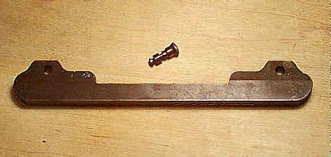
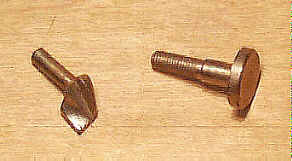 Around 1900, a chip
deflector (pictured to the left, with the cutter securing bolt to the right)
was added to the plane. As the name implies, the chip deflector's purpose is to
throw the shaving to the right of the plane instead of it going straight up the
iron, increasing the likelihood of the plane choking with shavings. The chip
deflector fits into the small hole just above the mouth and to the right side
of the main casting. The first planes to be shipped with the chip deflector
have one slight problem - the deflector and the depth stop can't be used
simultaneously since they both fit into the same hole of the main stock.
Stanley soon corrected this oversite by adding a provision for the depth stop
on the sliding section ca. 1910. The most commonly missing part for these
planes, without a doubt, is the chip deflector. They, and all the cam rests, #278 fences, #66
parts, #67 universal spokeshave parts, etc., are all resting comfortably in the
land of misfit parts.
Around 1900, a chip
deflector (pictured to the left, with the cutter securing bolt to the right)
was added to the plane. As the name implies, the chip deflector's purpose is to
throw the shaving to the right of the plane instead of it going straight up the
iron, increasing the likelihood of the plane choking with shavings. The chip
deflector fits into the small hole just above the mouth and to the right side
of the main casting. The first planes to be shipped with the chip deflector
have one slight problem - the deflector and the depth stop can't be used
simultaneously since they both fit into the same hole of the main stock.
Stanley soon corrected this oversite by adding a provision for the depth stop
on the sliding section ca. 1910. The most commonly missing part for these
planes, without a doubt, is the chip deflector. They, and all the cam rests, #278 fences, #66
parts, #67 universal spokeshave parts, etc., are all resting comfortably in the
land of misfit parts.
The depth stop for this plane differs from that used on the other combination planes like the #45. The earlier #50's depth stop has its post centered on the foot whereas the #45's has its post offset toward one side (the front) of the foot. Later #50's have the post offset toward the front of the foot, but the foot is longer than those of the #45. The post on the #45's stop has a larger diameter than the #50's. Check that a #45 stop hasn't been modified to fit the #50. To compound the confusion, Stanley equipped the plane with a beading stop starting around 1915; planes made after this date actually have two stops, with the beading stop being longer than the common depth stop. The beading stop is used just like the one for the #45 is.
The plane doesn't have steel skates like the #45 does. Instead, it has cast iron skates, like the #46, which are integral to the main stock and the sliding section. As is the case with any cast iron, check it carefully for cracks, welds, breaks, etc. Look around the main stock, where the cutter engages, for any stress cracks. This can be a problem area, and Stanley took measures to overcome the flaw with the addition of a reinforcement rib cast into the right side of the main stock ca. 1935.
The following cutters come with the plane:
Cutters First Offered in 1884
|
beading |
1/8", 3/16", 1/4", 5/16", 3/8", 7/16", 1/2" |
Cutters First Offered in 1902
|
grooving |
1/4" |
|
tonguing |
1/4" |
Cutters First Offered in 1914
|
ploughing |
5/16", 3/8", 7/16", 1/2", 5/8", 7/8" |
Cutters First Offered in 1936
|
ploughing |
1/8", 3/16" |
 There is
another plane that has the same number designation as this one. This particular
plane was not offered by Stanley as a #50, but was, instead, offered as
that model number by the Russell & Erwin Manufacturing Company of New
Britain, CT. It's generally thought that Stanley made the planes for Russell
& Erwin, who sold them as Miller's Improved Joiner's Plow, the No.
50. It is possible that Stanley designated the plane as the #50, since
it pre-dates the common configuration of the #50, but no advertising
literature has surfaced to indicate that Stanley actually sold it. Stanley was
manufacturing the #41-#44 Miller's Patent series concurrently to this
plane, and perhaps they didn't want to advertise a plane that did the same
function as those. Who knows? Regardless, the plane wasn't manufactured for
long, probably as a result of its delicate castings which certainly must have
proved to be difficult to make.
There is
another plane that has the same number designation as this one. This particular
plane was not offered by Stanley as a #50, but was, instead, offered as
that model number by the Russell & Erwin Manufacturing Company of New
Britain, CT. It's generally thought that Stanley made the planes for Russell
& Erwin, who sold them as Miller's Improved Joiner's Plow, the No.
50. It is possible that Stanley designated the plane as the #50, since
it pre-dates the common configuration of the #50, but no advertising
literature has surfaced to indicate that Stanley actually sold it. Stanley was
manufacturing the #41-#44 Miller's Patent series concurrently to this
plane, and perhaps they didn't want to advertise a plane that did the same
function as those. Who knows? Regardless, the plane wasn't manufactured for
long, probably as a result of its delicate castings which certainly must have
proved to be difficult to make.
This plane is a masterpiece in Victorian tool design and the art of casting and is one of the most prized objects in all of tooldom. The plane is elaborately cast with floral designs on its fence and main stock. There is a tiny turned rosewood knob fixed to the front left portion of the sliding fence. It can be found cast in iron and gunmetal, but with subtle design changes to each depending upon the material used to cast it - the most obvious difference is that the gunmetal castings have a pierced skate of scrolled motifs whereas the iron castings have a stippled skate. The gunmetal version also lacks the 'bridge' that spans the curved portion of the fence casting, between the two arms. The cast iron version was plated with a copper-colored surface, which is usually long gone when these planes rarely show.
#51 Chute Board Plane, 15"L, 2 3/8"W, 7 1/8lbs, 1909-1943.
 This is an L-shaped plane
(in cross-section), with a skewed blade (relative to the sole), and is designed
to clean up mitres on finer work. It has the typical Bailey adjustment
mechanism, and a rosewood tote, but no turned rosewood knob. The tote is nearly
impossible to grip with your left hand due to its position on the casting and
its leaning to the right. It also can be tough to grip with your right hand, if
you have hands that are the size of Sasquatch's. The tote is the same size as
those used on the larger Bailey bench planes, and can be had from one of those
planes if your tote is damaged.
This is an L-shaped plane
(in cross-section), with a skewed blade (relative to the sole), and is designed
to clean up mitres on finer work. It has the typical Bailey adjustment
mechanism, and a rosewood tote, but no turned rosewood knob. The tote is nearly
impossible to grip with your left hand due to its position on the casting and
its leaning to the right. It also can be tough to grip with your right hand, if
you have hands that are the size of Sasquatch's. The tote is the same size as
those used on the larger Bailey bench planes, and can be had from one of those
planes if your tote is damaged.
The body of the plane is ground square so that it can cut accurately as its sole rides on a flat surface. The plane was designed to be used with the chute board, #52, but could be purchased separately by those guys who had a board of their own.
The frog is a custom shape - you can't take a regular Bailey frog and make it fit this one, if your frog is screwed up. The frog is screwed to a rather thick cross-bar in the main casting of the plane's body. Check that this cross-bar isn't cracked. Because the frog doesn't mate to the main casting like a conventional bench plane's does, it's impossible to open or close the mouth of the plane. Further, a good portion of the cutter is unsupported because of the frog's design. The cutter is supported where it's most important, down at the mouth, but for the plane to work as intended, the cutter needs to be very sharp since a good amount of the tool's use is cutting across the grain. And, speaking of the mouth, its right side (when viewed from the sole) terminates in a circular fashion
The lateral lever, common on all the Bailey bench planes, plays an important role for this plane in the patternmaking trade. The lever can angle the iron, relative to the sole, by the desired amount to give the work being planed the proper draft. Draft is a very important part of patternmaking; draft is the slight angle given to a pattern so that the resulting casting can pop free from the sand.
This plane has been observed fitted with the typical World War II treatments; i.e., hardwood tote, hard rubber adjustment nut, no nickel plating on the lever cap, etc. If you find yourself in need of a replacement cutter or lever cap, both are identical to those used on a #6 and #7.
#52 Chute Board and Plane, 22"L, 9"W, 35lbs (17 1/2lbs 1909 on), 1905-1943. *
 This is Stanley's offering of the
#51 plane along with a heavy cast iron chute board,
which is designated the #52. Together, the two pieces sort of resemble a
meat slicer in appearance (it slices and dices ok, but don't buy it to
julienne). These two parts work very well, but are, unfortunately for the user,
very expensive.
This is Stanley's offering of the
#51 plane along with a heavy cast iron chute board,
which is designated the #52. Together, the two pieces sort of resemble a
meat slicer in appearance (it slices and dices ok, but don't buy it to
julienne). These two parts work very well, but are, unfortunately for the user,
very expensive.
Stanley advertised the board and the plane as being useful for patternmakers, cabinetmakers, printers, picture framers, and electrotypers. They even make a specific mention that "amateurs will also find this tool very useful." During the early 1920's, the board and plane were priced at $23.45. A common #5 was priced $6.05. It seems that there must have been some yuppy woodworker types even back then or Stanley wouldn't have mentioned the plane's amateur use in its propaganda.
The board is machined flat, and has a track into which the plane rides. The plane can sometimes stick in its track due to shavings and crud piling up in the track, and for the plane to cut accurately and effortlessly, this track needs to be clean. A drop of oil along it also keeps the plane sliding along. If you still find the plane tracking with difficulty, you can adjust the metallic strip along the right edge of the board. There are four screws that allow the strip to be adjusted latteraly when they are loosened; just loosen the screws, set the plane in the track, butt the strip against the rightmost edge of the plane, and then tighten the screws in a linear fashion as you move the plane along the entire length of the track
The surface of the board is ground flat and left unfinished, but the depressions cast into the board are japanned. The number "52" is cast into a depression of the track. The earliest models have the 1896 patent date cast into them. There are two countersunk holes bored into the beginning and end of the track. These holes allow the board to be attached to a piece of wood for mounting it in a fixture or on the bench. The board also has several holes bored in it to accomodate the adjustable stop. Three of the holes are predefined positions for the common angles of 90, 60, and 45 degrees; each of these holes has the degree incised near it. Into these predefined positions a t-shaped pin fits to make adjusting the stop easy. This t-shaped pin is often missing from the board.
 There is a stop on the
board, which can be adjusted through an arc of 45 degrees (degree markings are
incised along the arch-shaped portion of the stop). There are two holes in the
board at which the stop screw can be positioned; at the first hole the stop can
be adjusted from 45 to 90 degrees, while at the other the stop can be adjusted
from 45 to 0 degrees. Check the arched portion of the stop for any signs of
cracks, as it is susceptible to stress from the force applied to it by the
locking screw.
There is a stop on the
board, which can be adjusted through an arc of 45 degrees (degree markings are
incised along the arch-shaped portion of the stop). There are two holes in the
board at which the stop screw can be positioned; at the first hole the stop can
be adjusted from 45 to 90 degrees, while at the other the stop can be adjusted
from 45 to 0 degrees. Check the arched portion of the stop for any signs of
cracks, as it is susceptible to stress from the force applied to it by the
locking screw.
Attached to the stop is a plate that slides latterally relative to the track. This plate is adjusted based upon the setting of the stop so that the wood can have the proper support behind it as it is planed. When the stop is adjusted from 90 degrees to 45 degrees, the plate is slid away from the track lest the plane slam into it during operation. The plate is locked in place with a nickel plated wing nut.
Attached to the face of the plate is an L-shaped hold down clamp. This clamp is locked in position with the same kind of thumb screw as that used to secure the plate. The clamp is provided to hold the workpiece in position as it is shot true. The clamp has a hole drilled into it so that a screw may be driven into the workpiece for real holding power. The clamp is often missing on these boards, and its absence greatly diminishes the value (for collectors) of the tool.
Since this tool is designed to be very accurate, look for any signs of cracks and repairs anywhere on the board and plane.
#53
There ain't one. A plane, that is. There is a common as mud spokeshave that's numbered 53, but that's another subject for another day.
#54 Plow and Rabbet Plane, 9 1/4"L, various widths, 3 1/4lbs, 1939-1949. *
Only Stanley knows the reason why this plane was put into production as its utility is rather limited. Perhaps Stanley recognized the void in their numbering system, and decided that they ought to fill it with something useless. Or maybe they needed a plane to preceed (in the numbering sequence) that ghastly beast, the #55, in order to numb the potential customers as they scanned the company's catalogs. Whatever the reason, the plane didn't sell well and it's one of the scarcer planes in Stanley's former product line.
It's just another combination plane, whose appeal was limited due to its specific use. It really is a redundant plane, since it's identical to the #50, except that there is no depth stop provided on the sliding section (this plane suffers from a classic case of identity crisis); there is a "vestigal" bulge on the sliding section that's not tapped for the depth stop and its locking screw. The plane does use the depth stop on the right side.
Since the plane is designed only to groove/rabbet with the grain, it has no need for spurs, and there is no holder for the spurs cast into the right side of the main stock. If this isn't enough to identify your plane, the sliding section has the number cast into the arched portion.
The tool propaganda Stanley provided with this tool states that it came equipped with two pair of arms, one short pair and one long pair. When the plane is found, it's usually done so with just one pair of arms. The plane came fully nickel plated, but some japanned models were produced during the war years and it's possible to find mix and matched parts where the main stock is nickeled and the fence is japanned, for example.
The plane has the same cutter adjustment lever as that provided on the #50. Some recent tool literature states the plane came without the adjustment lever during its first years of production. I can't ever recall seeing one configured this way, and given the fact that the plane debuted a few years after the debut of the #50's cutter adjustment lever, a convincing argument that the #54 was offered only with the adjustment lever can be made since modified #50 bodies were used for this plane.
The following 8 ploughing irons come with the plane:
Cutters First Offered in 1939
|
ploughing |
1/8", 3/16", 1/4", 5/16", 3/8", 7/16", 1/2", 5/8" |
[ START ] | [ PREV] | [ NEXT ] | [ END ]
[ HOME ]
Copyright (c) 1998-2007 by Patrick A. Leach. All Rights Reserved. No part may be reproduced by any means without the express written permission of the author.